
Huawei P10 Lite LDC assembly replacement
Technical difficulty
Duration of the procedure
Number of steps in the tutorial
Replacement tools
Add all

Code: 13940

Read the instructions for replacing a broken or damaged Huawei P10 Lite display. If the screen on the phone is cracked, before you begin replacing it, you may wish to apply tape over it. By this small trick you will avoid shattering of the pieces, or bodily harm by accidentally transmitting fragments of broken glass into your eyes.
While replacing, the adhesive which attaches some parts of the smartphone will be compromised. Do not forget to add this adhesive, where required when reassembling.
Replacement parts for Huawei P10 Lite can be found on our offer in our e-shop in the replacement parts section. If you are interested in a service task for your Huawei, visit one of our branches.
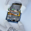
Step 1 Releasing rare cover
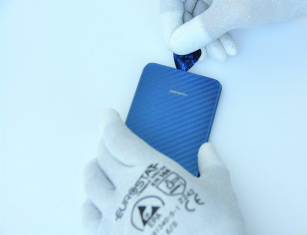
- use the tip of a opening triangle (pick) and insert it into the gap between the rare cover and the frame of the smartphone. Subsequently, move it along the perimeter of the phone, to separate to cover from the frame. If the connecting adhesive holds too firmly, you may help yourself by heating up using a hairdryer for approximately 60 seconds and then try again.
- After releasing the adhesive, flip over the cover – to the right side of the phone. By this you carefully separate it from the rest of the smartphone body
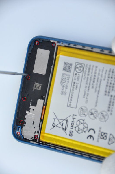
Step 2 Removing the Phillips #00
- Remove the Phillips #00 screws displayed in red in the photo
Step 3 Removing the cover bracket
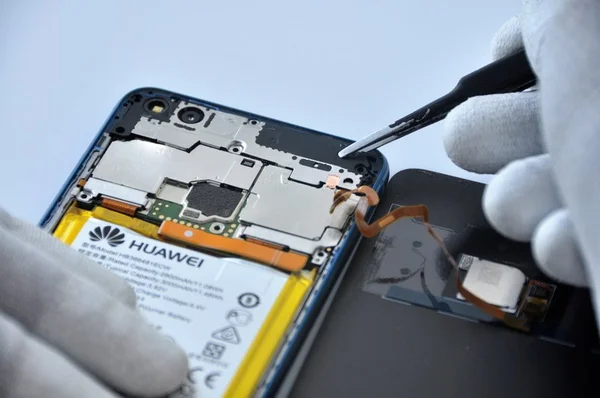
- Use tweezers to remove the cover bracket
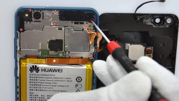
- Using the flat side of a spudger, disconnect the flexible cable leading to the fingerprint sensor.
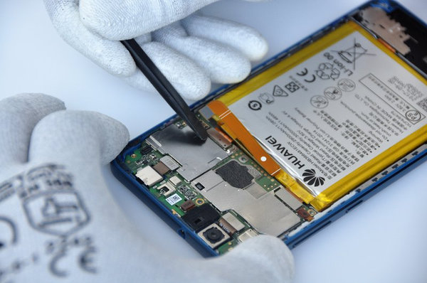
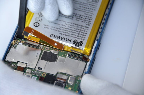
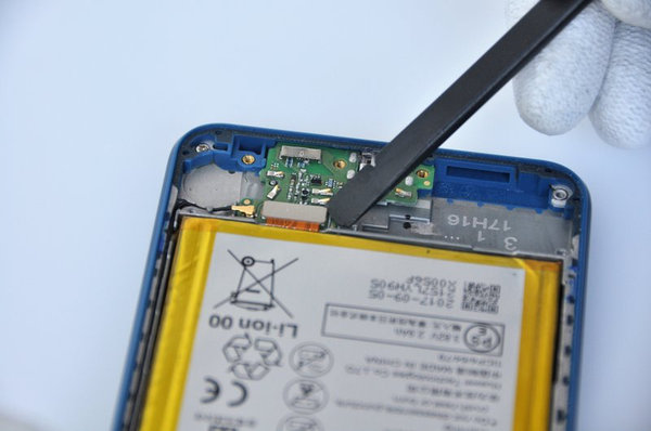
Step 4 Disconnecting flex cables from motherboard
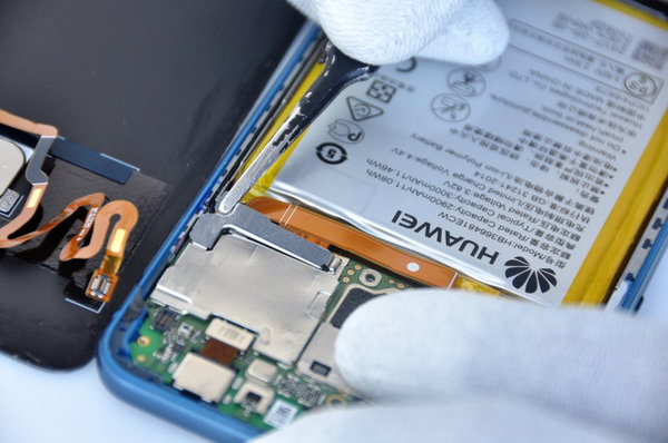
- Remove the metal bracket on the flex cable leading to the battery
- Now you can use a spudger to disconnect the flex cable itself
- Remove the meta bracket of the LCD flex cable and the side buttons connector
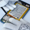
Step 5 Disconnecting the flex cables from the motherboard 2
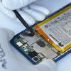
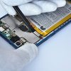
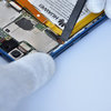
- Using a spudger, disconnect the interconnecting flex cable, LCD flex cable, side buttons flex cable, jack connector flex and RF cables
Step 6 Removing motherboard
- Use a spudger to carefully remove the motherboard, as shown in the pictures in the gallery
Step 7 Disassembling the speaker
- Unscrew the screws displayed in red
- Use a spduger to remove the speaker
Step 8 Disassembling the chargin module

- Us a spudger to disconnect the motherboard flex cable
- Separate the charging module as seen in the photo
- Install all the disassembled components into a new LCD assembly

Going Green
We are constantly improving our carbon footprint to protect our planet. Read more about how we are adapting our processes to reduce our footprint.